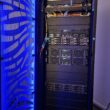
From an engineering standpoint probably one of the more interesting projects on this new homelab is the chilled door. It has so many aspects to it (Electricity, Plumbing, IT, …) that I have been really excited to work on this part.
The basic goal is the following: supply the chilled door with a constant flow of cold water so it can cool the hot air exhaust of the equipment in the rack back down to room temperature. Also I want to set up a monitoring system for the chilled door and it’s support systems so I can keep track of temperatures, water flow and fan speeds.
As a cooling source I will be using the thermal energy storage system my house is using for it’s heating and cooling. This system consists of a cold and hot water circuit which connects through heat exchangers to the house floor heating/cooling and radiators. Based on the cooling or heating need one of these circuits is leveraged to get to the desired temperature.
The cold circuit supplies water at a constant temperature of +- 7°C. This is the circuit to which I add an additional heat exchanger. The secondary side of that heat exchanger will connect to the chilled door and cool down the “hot” water returned from the door.


This is what the plumbing looks like. The black pipes on the right are the supply and return pipes of the cold water source. The white control valves with the white pipes are for the house systems. I tapped into the system just before that (red shut-off valves with pipes leading to the heat exchanger). I integrated two temperature sensors and a flow sensor in the same circuit.
The second system with thicker 1″ pipes forms the system for the chilled door. It also has two temperature sensors (supply and return) and a flow sensor. Since this is a completely seperate, closed ciruit, a pump is needed to generate the water flow.


Next up are some custom made cooling hoses that take te water back and forth from the support system to the door. Luckily the utility room is just on the other side of the wall from the room where the lab is located.


For the monitoring part of the system I had to create a small SNMP server which would probe for all sensor values. I have based it around an Arduino Uno + Ethernet shield + Proto shield. Out of the proto shield I built a custom I/O board with necessary components for connecting the sensors. It also has an onboard temperature sensor.
Everything is integrated into a control box located near the support systems. This box also houses the connections for pump power and control signals.

Here are the basic graphs I ran when powering up the system. I let the rack run for a while with just the fans on (so no water flowing) to get a baseline of the temperatures and let things heat up a bit 🙂
After that I turned on the building water and shortly after the pump (water flow graph is a good place to find the exact timing). It’s very interesting to see how the door temperatures and door controls react to that. (Have to check the external control pump and minimum curve settings since it’s still running reasonably fast while the door wants to have it slower as per the pump output curve).


