


With the “backbone” up and running it’s now time to expand the network to my home. For this to happen I needed let’s say an internet connection without the internet, which is off course a challenge since most internet providers want to sell the internet “service” and not the physical connection. In fact the most internet providers do not even own the physical cables in the ground. This is is the initial problem I needed to solve in the first place to get true redundancy.
The only way to achieve this was to reach out to physical infrastructure providers and hope anyone already had fibers in the ground nearby. This is where, amongst some others, I decided to also give Eurofiber a try and got lucky. They provide DIA but also a lot of datacenter connectivity and do it over their own physical infrastructure. One of their fiber routes happened to run only a few meters away from my front door which meant I really stood a chance now, as I didn’t want to pay 10.000’s of euro’s for digging a cable.
After going throug the different options, ranging from very expensive (like darkfiber) to affordable (but limited options) I settled on a L2VPN. This is a virtual Point to Point connection over their MPLS infrastructure with al the benefits of a regular L2 connections (such as creating your own VLAN’s etc) but without the cost of a physical (L1) connection. Bonus is that I can expand this virtial Point to Point to Point to Multipoint, which means I could add an extra connections at other locations and freely create VLAN’s between every location.
1. Physical cabling
After getting the contracts done it was time for action. At NIKHEF, Eurofiber already has presence which means I could make a cross-connect from their infrastructure to my router.
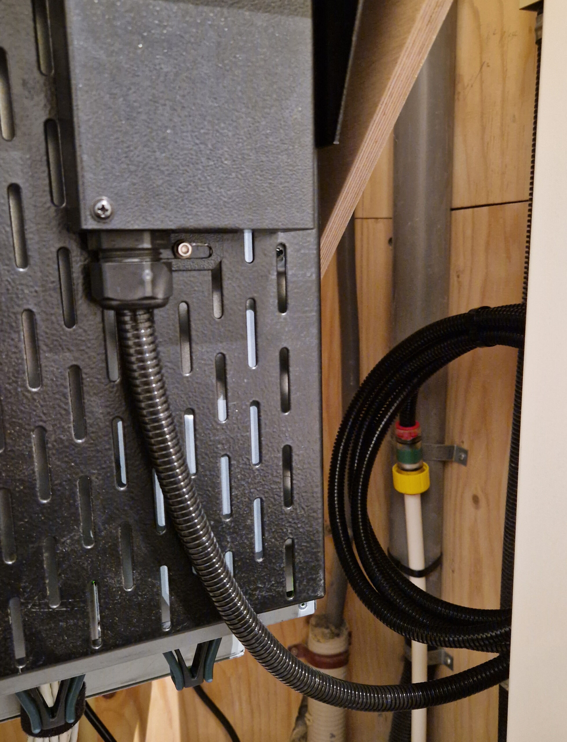
On the other side however, they needed to trench from their route to my home which meant getting permits and informing neighbours. But finally, a few months after the inital plan was made the day was there. I had a 4-strand fibre cable entering my home, which a few days later was terminated, measured and signed off by a technician.

2. Infrastructure
While waiting for the permits come through and the work being done I went forward and ordered all the necessary parts for the upgrade at home. I already had pulled some fiber from the “meterkast” to the server rack while doing the homelab upgrade last year. The runs consist of 4x Multimode 2-strand and 4x Singlemode 1-strand. The multimode fibers are used as a trunk to connect a switch which terminates all the devices at home and the singlemode fibers are intended for WAN connectivity. I now use one of them to connect the incoming Tweak fiber directly to the server rack / OPNSense box.
I initially wanted to get a second OPNSense box so I could terminate each WAN connection on a seperate firewall but while testing in EVE-NG I quickly ran into some issues / limitations and the upgrade got a bit bigger. After testing multiple brands and figuring out which ones would suit my needs AND have affordable licenses for home use, I bit the bullet on 2x Sophos SG-310 running Sophos Home as a HA Pair. I will probably dive into that in another post.
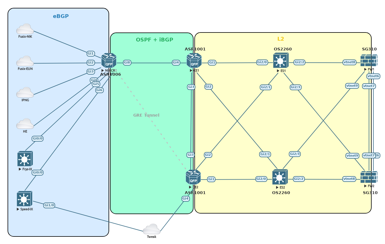
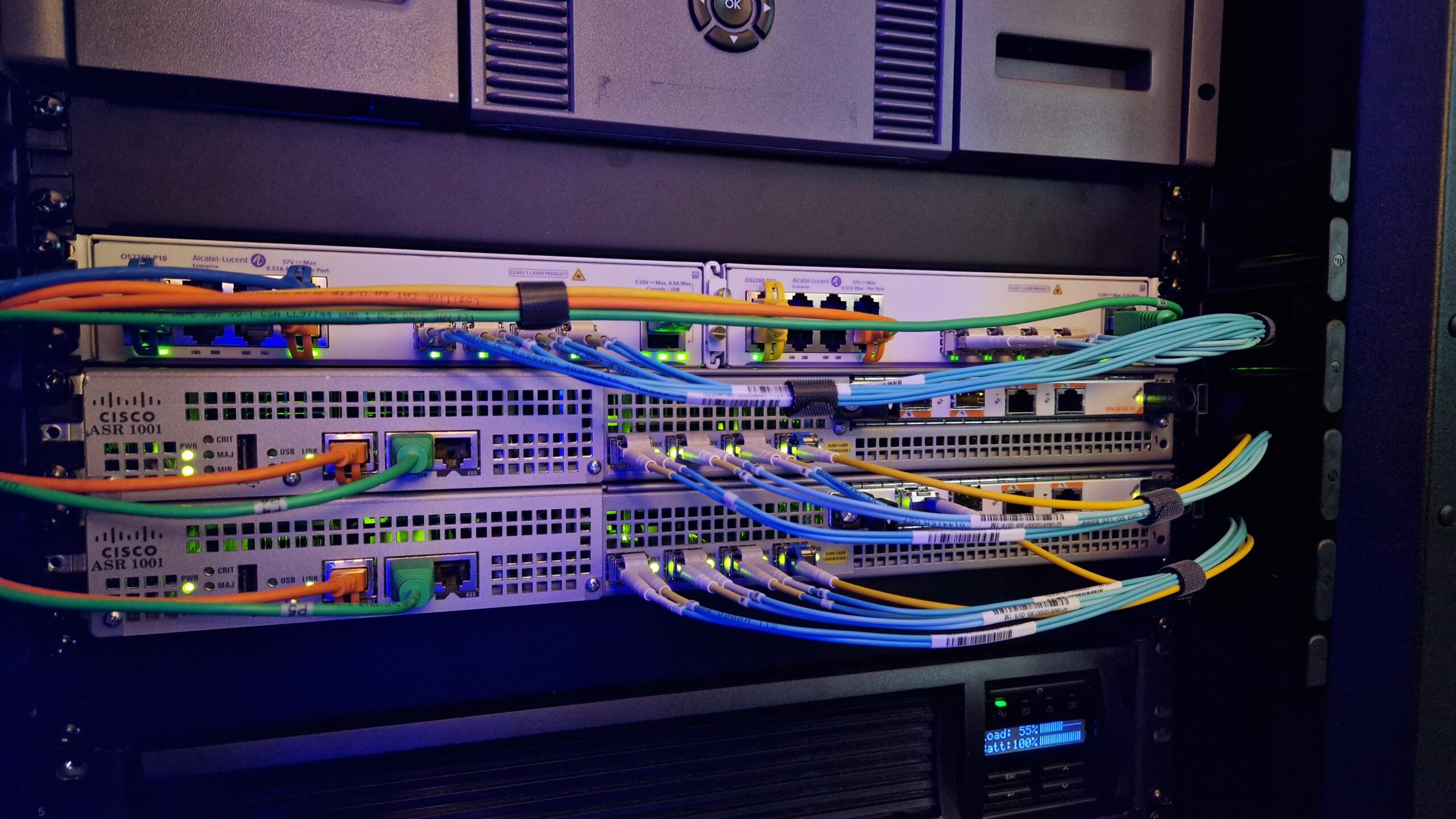
Router-wise I stuck with the Cisco ASR Range, a pair of ASR1001 in particular. As I also wanted a DMZ zone between the routers and the firewalls so I put in a pair of Alcatel Lucent OS2260-P10. They can be mounted as a two devices in 1U (which I really like because with all the upgrades I am almost out of rack space), have the ports I need and aren’t that expensive at all.
3. Configuration
I will be running BGP over OSPF for connectivity as I want to use part of my public IP ranges at home for full redundancy. Point to Point links will be created for basic connectivity. Loopbacks are set up as BGP router addresses. Connectivity between them established by using OSPF. BGP can then function on top of that using only the loopbacks so interface status does not necessarily affect BGP connectivity as there are multiple paths available.
Configuration for the new Eurofiber uplink is pretty easy due to the L2VPN. 82 will be the VLAN number for the public internet traffic.
NIK-CR1#
interface GigabitEthernet0/3/0
description EUROFIBER TO HOME
no ip address
negotiation auto
!
interface GigabitEthernet0/3/0.82
description HOME-CE1-GW
encapsulation dot1Q 82
ip address 194.31.131.80 255.255.255.254
ip ospf 1 area 1
ipv6 address 2A13:6EC0:C001:82::A/127
 ipv6 ospf 1 area 1
!
HOME-CE1#
interface GigabitEthernet0/0/3
 description EUROFIBER UPLINK
 no ip address
 negotiation auto
!
interface GigabitEthernet0/0/3.82
 description AS200232 HOME PUBIP
 encapsulation dot1Q 82
 ip address 194.31.131.81 255.255.255.254
 ip ospf 1 area 1
 ipv6 address 2A13:6EC0:C001:82::B/127
 ipv6 ospf 1 area 1
!
HOME-CE1#ping 194.31.131.1 source gi0/0/3.82
Type escape sequence to abort.
Sending 5, 100-byte ICMP Echos to 194.31.131.1, timeout is 2 seconds:
Packet sent with a source address of 194.31.131.81
!!!!!
Success rate is 100 percent (5/5), round-trip min/avg/max = 1/1/2 ms
HOME-CE1#
Backup link (my former Tweak main connection) is a bit more complex as it requires a GRE tunnel. Also, the uplink is still shared with the Zyxel router that Tweak delivers with their connection. This way I don’t have to worry about multicast configuration for now and IPTV can run independently of my lab config. This forwarding required the creation of Service Instances and BDI Interfaces. These are what would be VLAN’s and VLAN Interfaces on a regular switch.
NIK-CR1#
interface Tunnel82
description HOME-CE2-GW
ip address 194.31.131.82 255.255.255.254
ip ospf 1 area 1
ipv6 address 2A13:6EC0:C001:82::C/127
ipv6 ospf 1 area 1
tunnel source TenGigabitEthernet1/0/0
tunnel destination 82.197.218.231
!
HOME-CE2#
interface GigabitEthernet0/0/3
description TWEAK UPLINK
 no ip address
 no negotiation auto
 service instance 4 ethernet
  description TWEAK TV VLAN
  encapsulation dot1q 4
  rewrite ingress tag pop 1 symmetric
  l2protocol peer stp
  bridge-domain 4
 !
 service instance 34 ethernet
  description TWEAK INTERNET VLAN
  encapsulation dot1q 34
  rewrite ingress tag pop 1 symmetric
  l2protocol peer stp
  bridge-domain 34
 !
interface BDI34
description TWEAK INTERNET
ip address dhcp
!
HOME-CE2#
interface Tunnel82
 description GRE to NIK-CR1
 ip address 194.31.131.83 255.255.255.254
 ip ospf 1 area 1
 ipv6 address 2A13:6EC0:C001:82::D/127
 ipv6 ospf 1 area 1
 tunnel source BDI34
 tunnel destination 185.1.222.251
 !
HOME-CE2#ping 194.31.131.1 source tun82
Type escape sequence to abort.
Sending 5, 100-byte ICMP Echos to 194.31.131.1, timeout is 2 seconds:
Packet sent with a source address of 194.31.131.83
!!!!!
Success rate is 100 percent (5/5), round-trip min/avg/max = 2/2/3 ms
HOME-CE2#
Last thing needed is connectivity between the two CE routers, so that if the uplink to a router fails traffic can keep flowing:
HOME-CE1#
interface GigabitEthernet0/0/2
 description TO HOME-CE2
 ip address 194.31.131.84 255.255.255.254
 ip ospf 1 area 1
 negotiation auto
 ipv6 address 2A13:6EC0:E001:3::A/127
 ipv6 ospf 1 area 1
 !
HOME-CE2#
interface GigabitEthernet0/0/2
description TO HOME-CE1
ip address 194.31.131.85 255.255.255.254
ip ospf 1 area 1
negotiation auto
ipv6 address 2A13:6EC0:E001:3::B/127
ipv6 ospf 1 area 1
!
Loopbacks used for BGP:
NIK-CR1# (For reference as this one already exists)
interface Loopback0
 description ROUTER ID
 ip address 194.31.131.1 255.255.255.255
 ip ospf 1 area 1
 ipv6 address 2A13:6EC0:C001::F/128
 ipv6 enable
 ipv6 ospf 1 area 1
 !
HOME-CE1#
interface Loopback0
 description ROUTER ID
 ip address 194.31.131.86 255.255.255.255
 ip ospf 1 area 1
 ipv6 address 2A13:6EC0:E001:1::F/128
 ipv6 enable
 ipv6 ospf 1 area 1
 !
HOME-CE2#
interface Loopback0
 description ROUTER ID
 ip address 194.31.131.87 255.255.255.255
 ip ospf 1 area 1
 ipv6 address 2A13:6EC0:E001:2::F/128
 ipv6 enable
 ipv6 ospf 1 area 1
 !
And finally BGP itself, the ASR1001’s get default routes only as they can’t handle full table.
NIK-CR1#
router bgp 200232
 neighbor 2A13:6EC0:E001:1::F remote-as 200232
 neighbor 2A13:6EC0:E001:1::F description HOME-CE1
 neighbor 2A13:6EC0:E001:1::F update-source Loopback0
 neighbor 2A13:6EC0:E001:2::F remote-as 200232
 neighbor 2A13:6EC0:E001:2::F description HOME-CE2
 neighbor 2A13:6EC0:E001:2::F update-source Loopback0
 neighbor 194.31.131.86 remote-as 200232
 neighbor 194.31.131.86 description HOME-CE1
 neighbor 194.31.131.86 update-source Loopback0
 neighbor 194.31.131.87 remote-as 200232
 neighbor 194.31.131.87 description HOME-CE2
 neighbor 194.31.131.87 update-source Loopback0
 !
 address-family ipv4
  network 194.31.131.0
  no neighbor 2A13:6EC0:E001:1::F activate
  no neighbor 2A13:6EC0:E001:2::F activate
  neighbor 194.31.131.86 activate
  neighbor 194.31.131.86 next-hop-self
  neighbor 194.31.131.86 default-originate
  neighbor 194.31.131.87 activate
  neighbor 194.31.131.87 next-hop-self
  neighbor 194.31.131.87 default-originate
  exit-address-family
 !
 address-family ipv6
  network 2A13:6EC0::/32
  neighbor 2A13:6EC0:E001:1::F activate
  neighbor 2A13:6EC0:E001:1::F next-hop-self
  neighbor 2A13:6EC0:E001:1::F default-originate
  neighbor 2A13:6EC0:E001:2::F activate
  neighbor 2A13:6EC0:E001:2::F next-hop-self
  neighbor 2A13:6EC0:E001:2::F default-originate
  exit-address-family
  !
HOME-CE1#
router bgp 200232
 bgp log-neighbor-changes
 neighbor 2A13:6EC0:C001::F remote-as 200232
 neighbor 2A13:6EC0:C001::F description NIK-CR1
 neighbor 2A13:6EC0:C001::F update-source Loopback0
 neighbor 2A13:6EC0:E001:2::F remote-as 200232
 neighbor 2A13:6EC0:E001:2::F description HOME-CE2
 neighbor 2A13:6EC0:E001:2::F update-source Loopback0
 neighbor 194.31.131.1 remote-as 200232
 neighbor 194.31.131.1 description NIK-CR1
 neighbor 194.31.131.1 update-source Loopback0
 neighbor 194.31.131.87 remote-as 200232
 neighbor 194.31.131.87 description HOME-CE2
 neighbor 194.31.131.87 update-source Loopback0
 !
 address-family ipv4
  network 194.31.131.64 mask 255.255.255.240
  no neighbor 2A13:6EC0:C001::F activate
  no neighbor 2A13:6EC0:E001:2::F activate
  neighbor 194.31.131.1 activate
  neighbor 194.31.131.1 next-hop-self
  neighbor 194.31.131.1 prefix-list DEFAULT_ONLY in
  neighbor 194.31.131.87 activate
  neighbor 194.31.131.87 next-hop-self
  neighbor 194.31.131.87 prefix-list DEFAULT_ONLY in
  exit-address-family
  !
 address-family ipv6
  network 2A13:6EC0:E001::/48
  neighbor 2A13:6EC0:C001::F activate
  neighbor 2A13:6EC0:C001::F next-hop-self
  neighbor 2A13:6EC0:C001::F prefix-list DEFAULT6_ONLY in
  neighbor 2A13:6EC0:E001:2::F activate
  neighbor 2A13:6EC0:E001:2::F next-hop-self
  neighbor 2A13:6EC0:E001:2::F prefix-list DEFAULT6_ONLY in
  exit-address-family
  !
ip prefix-list DEFAULT_ONLY seq 5 permit 0.0.0.0/0
ip prefix-list DEFAULT_ONLY seq 10 deny 0.0.0.0/0 le 32
!
ipv6 prefix-list DEFAULT6_ONLY seq 5 permit ::/0
!
ip route 194.31.131.64 255.255.255.240 Null0
!
ipv6 route 2A13:6EC0:E001::/48 Null0
!
#HOME-CE2#
router bgp 200232
 bgp log-neighbor-changes
 neighbor 2A13:6EC0:C001::F remote-as 200232
 neighbor 2A13:6EC0:C001::F description NIK-CR1
 neighbor 2A13:6EC0:C001::F update-source Loopback0
 neighbor 2A13:6EC0:E001:1::F remote-as 200232
 neighbor 2A13:6EC0:E001:1::F description HOME-CE1
 neighbor 2A13:6EC0:E001:1::F update-source Loopback0
 neighbor 194.31.131.1 remote-as 200232
 neighbor 194.31.131.1 description NIK-CR1
 neighbor 194.31.131.1 update-source Loopback0
 neighbor 194.31.131.86 remote-as 200232
 neighbor 194.31.131.86 description HOME-CE1
 neighbor 194.31.131.86 update-source Loopback0
 !
 address-family ipv4
  network 194.31.131.64 mask 255.255.255.240
  no neighbor 2A13:6EC0:C001::F activate
  no neighbor 2A13:6EC0:E001:1::F activate
  neighbor 194.31.131.1 activate
  neighbor 194.31.131.1 next-hop-self
  neighbor 194.31.131.1 prefix-list DEFAULT_ONLY in
  neighbor 194.31.131.86 activate
  neighbor 194.31.131.86 next-hop-self
  neighbor 194.31.131.86 prefix-list DEFAULT_ONLY in
  exit-address-family
  !
 address-family ipv6
  network 2A13:6EC0:E001::/48
  neighbor 2A13:6EC0:C001::F activate
  neighbor 2A13:6EC0:C001::F next-hop-self
  neighbor 2A13:6EC0:C001::F prefix-list DEFAULT6_ONLY in
  neighbor 2A13:6EC0:E001:1::F activate
  neighbor 2A13:6EC0:E001:1::F next-hop-self
  neighbor 2A13:6EC0:E001:1::F prefix-list DEFAULT6_ONLY in
  exit-address-family
  !
ip prefix-list DEFAULT_ONLY seq 5 permit 0.0.0.0/0
ip prefix-list DEFAULT_ONLY seq 10 deny 0.0.0.0/0 le 32
!
ipv6 prefix-list DEFAULT6_ONLY seq 5 permit ::/0
!
ip route 194.31.131.64 255.255.255.240 Null0
!
ipv6 route 2A13:6EC0:E001::/48 Null0
!
Internal connectivity is done using redundant links (one to each Alcatel Lucent DMZ switch) and a HSRP address:
HOME-CE1#
interface GigabitEthernet0/0/0
 description TO HOME-ES1-GI1-1-9
 no ip address
 negotiation auto
 service instance 82 ethernet
 encapsulation dot1q 82
 rewrite ingress tag pop 1 symmetric
 l2protocol peer stp
 bridge-domain 82
 !
interface GigabitEthernet0/0/1
 description TO HOME-ES2-GI1-1-9
 no ip address
 negotiation auto
 service instance 82 ethernet
 encapsulation dot1q 82
 rewrite ingress tag pop 1 symmetric
 l2protocol peer stp
 bridge-domain 82
 !
interface BDI82
 description PUBIP
 ip address 194.31.131.65 255.255.255.240
 standby version 2
 standby 4 ip 194.31.131.67
 standby 4 preempt
 standby 6 ipv6 2A13:6EC0:E001:82:67::/64
 standby 6 preempt
 ipv6 address 2A13:6EC0:E001:82:65::/64
 ipv6 enable
 !
HOME-CE2#
interface GigabitEthernet0/0/0
 description TO HOME-ES1-GI1-1-10
 no ip address
 negotiation auto
 service instance 82 ethernet
 encapsulation dot1q 82
 rewrite ingress tag pop 1 symmetric
 l2protocol peer stp
 bridge-domain 82
 !
interface GigabitEthernet0/0/1
 description TO HOME-ES2-GI1-1-10
 no ip address
 negotiation auto
 service instance 82 ethernet
 encapsulation dot1q 82
 rewrite ingress tag pop 1 symmetric
 l2protocol peer stp
 bridge-domain 82
 !
interface BDI82
 description PUBIP
 ip address 194.31.131.66 255.255.255.240
 standby version 2
 standby 4 ip 194.31.131.67
 standby 4 preempt
 standby 6 ipv6 2A13:6EC0:E001:82:67::/64
 standby 6 preempt
 ipv6 address 2A13:6EC0:E001:82:66::/64
 ipv6 enable
 !
This concludes the configuration in a nutshell. Off course there are numerous access-lists and a fully seperate management network, but that would make this post way to long (if it isn’t already). Last but not least a graph I extracted from Grafana showing the impact in latency going from a regular connection to my own network. Awesome 🙂


Do you plan to keep renewing the RIPE membership?
Yes as long as I want my own AS and IP blocks I need to.